MoPower UPS super capacitor setup and testing - Raspberry Pi
October 9, 2016
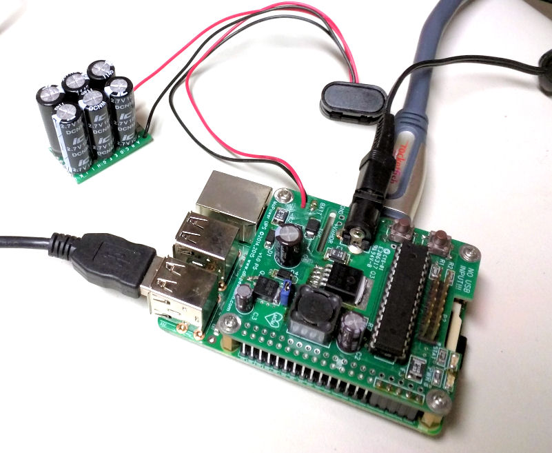
Here is an example of using a Raspberry Pi backed up with a supercap powered Mopower UPS!
Safety notice! You should be careful with supercaps, as they can discharge a lot of power in a short amount of time. The MoPower UPS has a polyfuse on the battery input for protection, but you must be careful when handling supercaps and connectors to avoid a short circuit. If in doubt get assistance.
Polarity Warning on 9v snaps! Please note that most 9v block battery snaps have their wire polarity colors in relation to it being used on the LOAD side. When these snaps are used on the SOURCE side the red and black wires will likely be reversed! Please ensure you properly wire your supercapacitors!
In the last several years supercap capacity has gone up and costs have come down, making them suitable for an increasingly broad range of applications. It provides a marked increase in lifespan and number of cycles verses a battery application. We will build and test a simple supercap 'battery' for use with our Raspberry Pi and the MoPower UPS to examine its capabilities.
We are using a Pi 3 connected to a keyboard and HDMI monitor for this test. It is mostly idle and uses approximately 272mA at 5v, or about 1.36 watts.
Capacitor working voltage
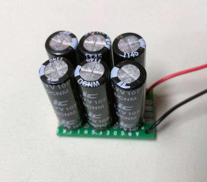
Super capacitors are commonly available in the 2.7 volt range, on applications that require higher voltage we have to built a 'battery' pack using several super capacitor 'cells'. For this setup we picked up six 10 farad 2.7 volt super capacitors giving us a peak working voltage of (2.7v * 6) = 16.2 volts. This gives us a good working voltage for both an automotive 12v system and regular 9v or 12v wall adapters.
Capacity - Farads
The formula for capacitors in series is (1/CTOTAL) = (1/C1) + (1/C2) + (1/C3)... If the capacitors are all the same we can just divide the capacity of one by the number of capacitors in series, which gives us 10F / 6 = 1.67 Farads.
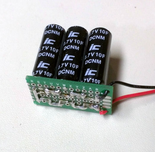
Equalizing resistors
There is one minor issue we have to account for in our super capacitor series 'battery'. Differences in capacity and leakage current will cause differences in charge voltage of the cells in our series pack, and we do not want to exceed the working voltage of these cells. We are using all identical capacitors, so we generally do not have a wide variance, but we still have manufacturing tolerances to account for. We can add a simple balancing circuit using resistors in parallel with each cell, this resistance will dominate the leakage current and keep the individual cells more balanced. As a general guideline we can size the balancing resistors to be about 10-50 times the leakage current of our cells. In our case it is 0.03mA (the leakage current will be in the datasheet) so we will use 0.03mA x 50 or about a resistor that gives us 1.5mA. To get the resistor value we use ohms law and our max working voltage.. 2.7v/0.0015 = 1,800 ohms. The exact value is not important in our particular application, as we are using a resistor with a much higher current then our capacitor leakage. A resistor in the 1k-3k should work fine.
The short
There is another design consideration when using super capacitors that you should be aware of. When charging a supercap that is at 0v it will appear to be a short to your power supply. Your power source must be capable of dealing with this. We are hooking up our supercap to the MoPower UPS battery connector, so this automatically gives us a charge current limited to 52mA (our default AA battery trickle charge current). Our supercap charger over-current protection is automatically built it!
Run Times
We will be using our supercap in a 12v automotive system and we will have about 14 volts input. The trickle charge regulator has a 1v drop which results in 13 volts to our supercaps. Because of voltage drop in our DC converter and to give our system enough time to shut down, we use 7v as our ending voltage. Our current use at 14v is about 130mA. Our runtime calculation then becomes..
capacitance x (starting volts - ending volts) / I = seconds runtime
1.67F x (13v-7v) / 0.130A = 77 seconds
Now for the test.. we power up the UPS and let it charge our supercap battery to 13v. Cutting power and drawing from the supercap we get a runtime of 48 seconds. Why the discrepancy? The simple formula we used assumed a constant current draw, but since most of our current draw is from a DC-DC converter, as our voltage drops our current will increase. The opposite would happened with a simple resistive load, as voltage drops current would drop in that case.
We can take current measurements at different voltages or calculate our average current over the discharge voltage range, but it's easier to use the formula and get our average current.
1.67F x (13v-7v) / 48 seconds = I
1.67F x (13v-7v) / 48 seconds = 0.209 A
This indicates our Pi uses an average of 209mA over the discharge range of 13 to 7 volts. Dropping our input voltage to 7v gives us about a 250mA current draw, confirming our calculation.
Adjustments to the UPS
Drawing our supercap down to 7v before starting a shutdown might not be the best idea. The Pi must be given enough time to properly shut down. At a 7v shutdown, our Pi 3 with Jessie lite was not always able to successfully power down before our supercap ran out of power. Setting our shutdown voltage level on the UPS to 9v (using SETTINGS_UPS_BATT_SHUTDOWN_VOLTS=9.00) gave us a sufficient amount of time to properly shut down. This gives us about a 35 second run time before the shutdown process begins. You may need to adjust this voltage if your shutdown takes longer then usual. The UPS will automatically start our Pi back up when the power returns and our supercap charges to a sufficient level (also configurable).
Conclusion
Our setup resulted in 35 seconds of useful runtime on 1.67 Farads of super capacitors running a Pi 3. A model A Pi or Pi Zero should at least double to triple this runtime!
Our capacitors were about $2 each for a cost of $12 for the capacitors, generally higher then batteries but fairly reasonable. If you can work with these run times they provide a power solution that will last many times longer then a battery. Projects that may benefit include automotive, basic UPS, extreme temperature applications, or where power cycling is too frequent.
Please support our efforts and buy a Mopower UPS!
Thank you!